![]() |
 

|
 |
![]()
![]()
| Electromagnetic study of the ITER thermalshield |
 Completed orders:
ITER Team (Garching, Germany) - International Thermonuclear Experimental Reactor
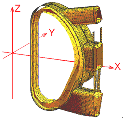
The analysis is based on a 3D finite element (FE) representation of the thermal shield components using a thin shell approximation. The VVTS was modeled as a single-layer shell. The CTS/TTS/STS structures were modeled with a set of 3D single-layer plates with reinforcement ribs for the panel design option.
The analysis has been performed with the use of a 3D FE code TYPHOON [1] developed at the Efremov Institute. TYPHOON allows a transient electromagnetic analysis using an FE representation of thin shell structures in an integral formulation to model arbitrary conducting walls of complex geometry.
VVTS was simulated separately from the remaining thermal shield due to accuracy requirements and extensive computational efforts involved.
For the same reason, the CTS/TTS/STS structures were divided into three separate models: CTS/TTS, CTS/TTS/STS, and the alternative self-standing CTS/TTS. Due to the symmetry, the calculation model was reduced to a 20-degree sector. The effect of eddy currents induced in VV dominates mutual induction of the panels. This allowed CTS/TTS/STS to be described by a combination of 2 sub-models: CTS/TTS sector #1 (Fig.1b) and CTS/TTS/STS sector #2 (Fig.2b) to simplify simulation and reduce a runtime.
Three resulting FE models have been developed to analyze the two CTS/TTS design options:
1) Cryostat thermal shield / transition thermal shield (CTS/TTS) (Fig. 1b);
2) Alternative cryostat thermal shield / transition thermal shield (CTS/TTS) (Fig.2a);
3) Cryostat thermal shield / transition thermal shield / support thermal shield (CTS/TTS/STS) (Fig.2b);
The Vacuum Vessel Thermal Shield (VVTS) shown in Fig.1a was modeled separately via thin shells.
VVTS is designed as a set of panels without electric contact. Each panel consists of a 35mm thick joint and two inner steel plates, 10 mm and 5 mm thick. A panel was modeled by a shell, which consists of two portions: inner and outer, as shown in Fig. 3. The outer shell simulates the joint. To imply the resistivity, the effective thickness was taken as 35mm for the outer portion of shell and 15mm for the inner portion.
Resistivity is dictated by the material properties and temperature of the conductor. At an operating temperature of 80K VVTS made of steel 304L has a resistivity of 5.44Х10-7 OhmЈm. For CTS/TTS and CTS/TTS/STS the resistivity was assumed constant and taken as 5.6Х10-7 OhmЈm. The thicknesses of the models components varied from 6mm to 50mm to reflect the realistic design.
Beside the single layer thermal shield and the double-walled vacuum vessel the calculation model includes the plasma, the system of toroidal field (TF) and poloidal field (PF) coils to take into consideration the ripple effect.
An important point in the model development is a topological analysis of an FE mesh. To provide adequate modelling in a thin shell formulation the first Kirchhoff law should be satisfied for furcated multi-connected conducting shells. The computational region is decomposed into simply connected domains separated with conventional sections and then reconstructed so that to produce a system of ordinary differential equations in terms of an electric vector potential. In the thin shell approximation the electric vector potential has a single component to express the eddy current density
[2, 3, 4]. This allows solving a high-dimensionality problem with a dense matrix.
In the study the global Cartesian coordinate system (X,Y,Z) was used with the origin at the center of the ITER machine.
VV geometry and location remain invariable for all calculation models.
The simulations performed for a wide range of operating modes allow one to predict the most dangerous conditions when a peak surface density of the normal ponderomotive force would occur. Critical time points have been determined for all TS components. The CD27ms is expected to produce most severe load on the CTS/TTS structure, both for the panel and self-standing designs. The most loaded condition for CTS/TTS/STS is the slow downward VDE. The most critical EM loads on VVTS are reached at different scenarios of plasma discharge, i.e. toroidal force and EM pressure - at CD27ms, vertical torque moment - at fast downward VDE.
The distributed EM loads obtained from this analysis have been transferred into equivalent forces concentrated at the nodes of the reference FE mesh. For the distributed force density
 this procedure practically implies integration over all space. this procedure practically implies integration over all space.
 Here
Here  is the shape function,
  is the element volume,
The resulting nodal loads have been used as inputs for a subsequent structural analysis. To transform distributed loads into their nodal equivalents a code NFORCE [9] has been applied. NFORCE is applicable for most popular types of 2D and 3D FE representations and capable of producing output data in different formats including the ANSYS format.
The estimates of EM loads are of primary importance in selecting the design of thermal shield panels, supports, and joints and dictate the design concept of the thermal shield.
An overall reduction in size of the ITER machine has drawn attention back to the concept of the self-standing thermal shield. The detailed investigation of expected EM loads followed by a mechanical study confirms the advantages of this design.
The EM analysis performed has driven the conceptual design of the ITER thermal shield [10]. The results of the analysis will be included in the FDR/DDD 2003-2004.
Read the article ї
|
|
 |
![]()
 ![]() |
![]()
Germany (headquarters): Alphysica GmbH. Unterreut, 6, D-76135, Karlsruhe, Germany,
Phone: +49 (0)163 904-85-61,
Fax: +49 (0)7219 444-26-55, E-mail: info@alphysica.com
![]()
USA: Alphysica Inc. 414, Jackson street,
San Francisco, CA 94111, USA,
Phone/Fax: +1 415.230.23.63, E-mail:usa@alphysica.com
![]()
Russia: Alphysica Ltd. 55, ul. Mayakovskogo, 191025, St.Petersburg, Russia,
Phone/Fax: +7 (812) 335-95-04, E-mail: russia@alphysica.com
Copyright © 1994-2010
![]()
| |
|
![]() |


