![]() |
 

|
 |
![]()
![]()
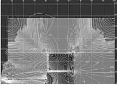
| Effect of deformations caused by the ponderomotive force on magnet system quality |
 Completed orders:
Joint Institute of Nuclear Research (Dubna, Russia) Ц cyclotron DC60
ITER Team (Garching, Germany) - International Thermonuclear Experimental Reactor
Confidential (Genue, Italy) Ц MRI tomograph
Efremov Inst. (St.-Petersburg, Russia) Ц cyclotron CC18/9
Efremov Inst. (St.-Petersburg, Russia) Ц cyclotron CC12
Kurchatov Institute (Moscow, Russia) - T15M tokamak
W7X team (Garching, Germany) Ц W7X Stellarator
Deformations estimates were then applied to correct the field configuration. Distributed electromagnetic loads, calculated with the use of specially developed software package, were transformed into equivalent nodal forces using the program NFORCE and served as the inputs suitable for stress-strain state calculations (for ANSYS package as an example).
The main steps in the DC60 cyclotron stress analysis (as an example) were:
1. A 3D field simulation at given coil currents. The calculation region was taken as a part of the space R 3 . The simulation was made with the use of the program package KOMPOT [4]. A detailed finite-element (FE) model of the magnet system was developed so as to provide realistic geometry description and take into consideration the  curve , where m is permeability, curve , where m is permeability,  is the field strength vector. is the field strength vector.
2. The magnet FE model was used as a basis to built an ANSYS model for the stress-strain analysis. Both models had the same reference mesh used to define distributed loads associated with ponderomotive forces.
3. The magnet FE model was applied to calculate the volume force density on ferromagnetic and conducting components of the magnet system. Distributed ponderomotive loads were transformed into their nodal equivalents with the use of the program NFORCE [5]. The results were presented in a format suitable for ANSYS calculations. The calculation of nodal loads was implemented as integration of the finite elements over a volume:  , where , where  is the ponderomotive force density vector, N t is the shape function, is the volume of finite element ( e ). An allowance was made for the specifics of the FE meshes for the magnetostatic and stress calculations. is the ponderomotive force density vector, N t is the shape function, is the volume of finite element ( e ). An allowance was made for the specifics of the FE meshes for the magnetostatic and stress calculations.
4. Results of the stress analysis were used to correct the magnet model with regard to the predicted deformations and re-calculate the magnetic field distribution.
To finalise the analysis, possible compensation for the strain effects in the magnet working zone was studied. As the compensation actions, variations of coil currents and shaping of the ferromagnetic components were proposed.
Read the article ї
|
|
 |
![]()
 ![]() |
![]()
Germany (headquarters): Alphysica GmbH. Unterreut, 6, D-76135, Karlsruhe, Germany,
Phone: +49 (0)163 904-85-61,
Fax: +49 (0)7219 444-26-55, E-mail: info@alphysica.com
![]()
USA: Alphysica Inc. 414, Jackson street,
San Francisco, CA 94111, USA,
Phone/Fax: +1 415.230.23.63, E-mail:usa@alphysica.com
![]()
Russia: Alphysica Ltd. 55, ul. Mayakovskogo, 191025, St.Petersburg, Russia,
Phone/Fax: +7 (812) 335-95-04, E-mail: russia@alphysica.com
Copyright © 1994-2010
![]()
| |
|
![]() |


