![]() |
 

|
 |
![]()
![]()
| 3D numerical simulations of electromagnetic loads on an ITER divertor cassette |
 Completed orders:
ITER Team (Garching, Germany) - International Thermonuclear Experimental Reactor
The special code was developed to numerical simulation of eddy currents in interconnected thin conducting shells. Multiple inter-connections and branching of the shells helps to simulate complicated structures. The code uses a finite element representation in an integro-differential formulation in terms of a vector electric potential referred as the T-W method. With this method, the mesh should cover the only conducting domains, and doesn't need to cover non-conductive domains. Discretization of the initial integro-differential equation yields a dense matrix that involves extensive computational efforts and somewhat restricts the method's applicability.
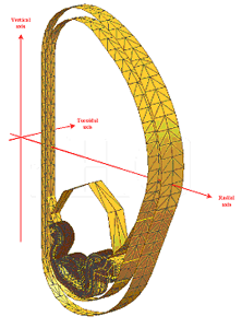
A single FE model in a thin shell approximation has been employed to calculate all listed EM loads. The shells are triangulated via simplex-elements as shown in Figure 1. Due to the cyclic symmetry, the model is limited to a 1/54 of the ITER machine. It describes the double-walled vacuum vessel, a divertor cassette, the plasma, poloidal and toroidal field coils. Additional virtual elements were added to simulate the Halo current path closed through the plasma periphery. Currents in these virtual elements are assumed to vary in compliance with prescribed Halo currents.
Modeling of conducting structures
The vacuum vessel (VV) is modelled by two thin shells missing mutual electrical contact. The divertor model is shown in Figure 2. It describes the cassette body and plasma-facing components, namely the dome with reflector plates, inner and outer vertical targets [5].
The plasma-facing components are modelled in fine details so that to closely describe the actual design. There are stainless steel supports, fasteners, and poloidally elongated bronze monoblocks with internal cooling channels, covering the plasma-facing surfaces. The poloidal elements are separated in the toroidal direction with gaps to restrict the eddy currents as possible, and this is reflected in the EM model. By other words, the model reflects electrical anisotropy of the plasma-facing components, with relatively higher conductivity in the poloidal direction.
Modelling of PF and TF coils
The calculating model represents 6 CS sections, 6 PF coils and 18 D-shaped TF coils. Geometrical parameters of the coils are taken from [5].
Amere-turns of each TF coils are 9.128MA. This corresponds to the toroidal field 5.3T at R=6.2m. A toroidal field is co-directional with the toroidal plasma current, that means clockwise relative the machine's vertical axis as viewed from the above. Input graphs for the CS and PF coil currents at both scenarios were specified by the ITER Joint Central Team (JCT).
Modelling of the plasma behaviour
The plasma is represented by ~800 elementary current loops with independently varied currents, provided by JCT as input data. The toroidal plasma current flows clockwise relative the machine's vertical axis, that means co-directed with the toroidal field.
A toroidal magnetic flux generated by the plasma current is simulated with the use of a virtual toroidal solenoid located in the middle of the vacuum vessel. The solenoid generates a toroidal magnetic flux, that is a sum of a pure diamagnetic flux and a pure paramagnetic flux. The paramagnetic flux is co directional with the main toroidal field while the diamagnetic flux is opposite. In typical operating modes, paramagnetic flux dominates and dictates the direction of a resultant magnetic flux, i.e. clockwise relative the machine's vertical axis. The diamagnetic flux drops to zero at the end of the thermal quench, and the paramagnetic flux disappears at the end of plasma current quench.
Evolutions of the toroidal magnetic flux and toroidal plasma current at the fast/slow downward VDE are taken as specified by the ITER Joint Central Team.
Locations of the inlet and outlet areas for the Halo current are designated near supports of the blanket modules # 1 and #17, respectively (ref. Figure 1). Time variations of the Halo currents are prescribed by the JCT. Peak Halo currents is 4.9MA for the fast scenario and 6.9MA for the slow one.
- A dominant portion of total EM forces, radial and vertical, applied to the ITER divertor cassette during the downward VDE is one associated with Halo currents and variations of the toroidal magnetic flux.
- A dominant portion of total EM moments, radial and vertical, is one caused by variations of the toroidal plasma current.
- As for slow downward VDE, the maximal radial and vertical EM forces are reached at the time when the Halo current peaks (6.9МА). The maximum radial force is -837kN and the vertical one is -1.89MN.
- The maximal radial moment of -1.11MNЧm and the vertical one of -4.38MNЧm are expected at the fast downward VDE at the end of the current disruption when the highest rate of the plasma current decrease of -1107MA/s occurs.
- The stress analysis performed on the basis of the calculated EM loads predicts mechanical overloading on the fasteners of the vertical targets and the dome at the fast downward VDE.
- A modification in the design of the vertical targets and the dome is recommended to reduce the loads. An electrical gap is proposed at the symmetry plane of the cassette to cut the loops of eddy current generated by the toroidal plasma current variations and consequently lower EM loads on these components
Read the article »
|
|
 |
![]()
 ![]() |
![]()
Germany (headquarters): Alphysica GmbH. Unterreut, 6, D-76135, Karlsruhe, Germany,
Phone: +49 (0)163 904-85-61,
Fax: +49 (0)7219 444-26-55, E-mail: info@alphysica.com
![]()
USA: Alphysica Inc. 414, Jackson street,
San Francisco, CA 94111, USA,
Phone/Fax: +1 415.230.23.63, E-mail:usa@alphysica.com
![]()
Russia: Alphysica Ltd. 55, ul. Mayakovskogo, 191025, St.Petersburg, Russia,
Phone/Fax: +7 (812) 335-95-04, E-mail: russia@alphysica.com
Copyright © 1994-2010
![]()
| |
|
![]() |


