![]() |
 

|
 |
![]()
![]()
| Numerical simulation for field formation in cyclotron dc60 |
 Completed orders:
Joint Institute for Nuclear Research (Dubna, Russia) - cyclotron DC60
For DC60 the numerical procedure of field formation included 5 stages.
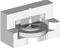
1. At the first stage basic parameters of the magnet system were determined from the magnetooptic calculations. Fig.1 illustrates the reference configuration of the magnet system.
2. The second stage involved the development of a realistic 3D model for the DC60 magnet system. The model used detailed descriptions of the magnet geometry, media interfaces, and non-linear properties of steel. For initial calculations a standard near-realistic B-H curve was used as reference. Then steel properties were corrected using the results of magnetic measurements on samples of steel used in the fabrication of DC60 (see Ref. [4] for details). The curves В(Н), m(Н), m(В), ¶m / ¶ H ) obtained for the real magnet were used to simulate the expected field distribution and to choose the shimming method. Figures 2,3 present a part of the finite-element model of DC60 magnet system (magnetic circuit and coils only). The model covers a 1/8 of the magnet system and includes boundary conditions with respect to the magnet symmetry. The external boundary for the calculated region was taken so that to avoid the influence of the given boundary conditions on the field behaviour inside the working zone and at a distance from the magnet. The finite-element mesh has about 350000 nodes.
3. The finite-element model was applied to preliminary analyse a spatial field distribution at different coil currents. The magnetooptic analysis gave required isochronous curves for different field levels. The next step was to vary geometrical parameters in order to calculate the influence functions [2] for different magnet components and select the method of field formation. From the results of the calculation, the axial shimming by adjusting the sector thickness near the median plane was chosen to form a desired field distribution in DC60.
4. The influence functions obtained were used to form an isochronous field with the accuracy required at the basic field level of 1.45Т. Figures 4, 5 show calculated field distributions over typical cross sections for the optimised magnet configuration. Figure 6 shows the field distribution in the reference and optimised magnet system in comparison with the desired isochronous field. The formation of the optimised field included a set of iterations. Each iteration had a prediction phase and a correction phase. During the prediction phase the magnet geometry was varied slightly, and a new magnet circuit configuration was formed from the field distribution of the previous iteration and known influence functions having regard to the required isochronous curve. In the correction phase, a field distribution was calculated for the obtained magnet configuration taking into account the saturation effect. After several iterations, the trajectory analysis was performed on the basis of the generated field map to correct the isochronous curve and to close the solution of the self-consistent problem. If the iterated geometry differed markedly from the reference configuration, the influence functions were re-calculated.
5. For the optimised magnet configuration, a field distribution was calculated at 3 field levels. Also, at the same field levels, the correction coil influence was estimated. At the final step, an impact of deformations associated with ponderomotive forces were calculated and stress-strain analysis was performed [5].
The proposed numerical method allowed effective field formation in DC60 taking into consideration non-linear properties of steels used in the fabrication of the real magnet. The influence function obtained made it possible to estimate manufacture/assembly tolerances, which will be used for magnetic measurements and magnet adjustment.
Read the article »
|
|
 |
![]()
 ![]() |
![]()
Germany (headquarters): Alphysica GmbH. Unterreut, 6, D-76135, Karlsruhe, Germany,
Phone: +49 (0)163 904-85-61,
Fax: +49 (0)7219 444-26-55, E-mail: info@alphysica.com
![]()
USA: Alphysica Inc. 414, Jackson street,
San Francisco, CA 94111, USA,
Phone/Fax: +1 415.230.23.63, E-mail:usa@alphysica.com
![]()
Russia: Alphysica Ltd. 55, ul. Mayakovskogo, 191025, St.Petersburg, Russia,
Phone/Fax: +7 (812) 335-95-04, E-mail: russia@alphysica.com
Copyright © 1994-2010
![]()
| |
|
![]() |


